
DIY Info
DIY Info for AE modular
AE modular is a quite nice platform for every DIYer, either if you do analog electronics or you are working with microcontrollers like Arduino / Atmel, ARM etc.The whole system is working entirely on 5V, the common voltage used in many DIY projects and directly compatible with usual microcontrollers.
BUS CABLE
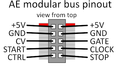
All modules are connected with a 10-pin ribbon cable that runs below the modules. Each module is plugged onto this bus cable with a 10-pin connector.I you want to use this bus for own modules, you find the pin setting below. The red strip marks the +5V side (on two pins); the next 2 pins are ground (GND), the remaining 6 pins are CV/GATE, START/STOP/CLOCK and CTRL (MIDI controller #20) usually fed by the MASTER module.
As already mentioned, AE modular works entirely on +5V. For the several signal types this means the following:
- CV signals are also in the range of 0...5V; inputs as well as outputs.
- Audio signals are usually "centered" to +2.5V, the typical audio level is 3V overall (so the audio swings between +1V and +4V). Some outputs like pulsewaves on the oscillator modules use the full range of 0-5V.
- Gate/trigger signals are 5V positive.
- The output resistance is usually 1k. So nothing bad happens if an output is connected to ground or two outputs are directly connected (in fact, they will be summed / mixed).
More information on the Wiki and the Forum
There is a whole section on the wiki dedicated to DIY.Please visit: https://wiki.aemodular.com/#/diy/
Also the forum has a large community of inventors and they present and discuss their projects here: https://forum.aemodular.com/board/8/diy-building